Verified for the agreed car
The adapter and ECU configuration are prepared around the confirmed IAW 1AP vehicle pinout, not around a generic universal wiring assumption.
Application-specific plug-and-play ECU solution for PSA IAW 1AP based projects, including Citroën Saxo VTS and Peugeot 106 motorsport builds, prepared around verified vehicle pinout, base map configuration and direct startup support.
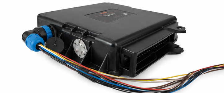
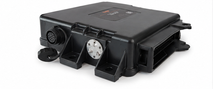
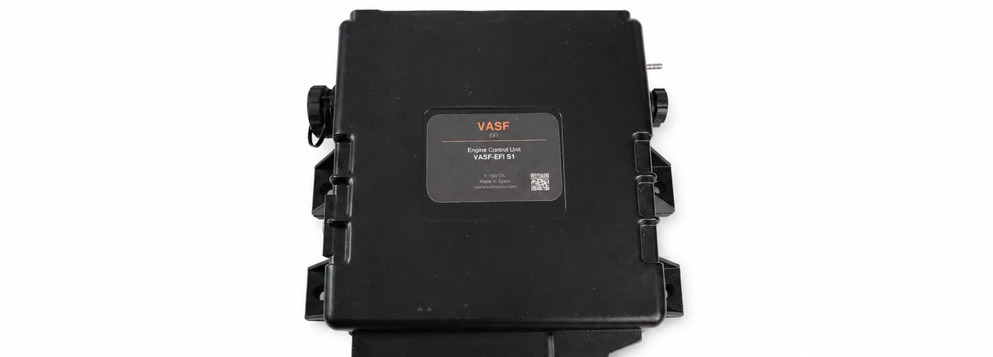
Based on the tested VasfEFI S1 platform, this version keeps the OEM IAW 1AP connector interface and adds an auxiliary connector for extra motorsport functions, instead of being sold as a generic universal ECU.
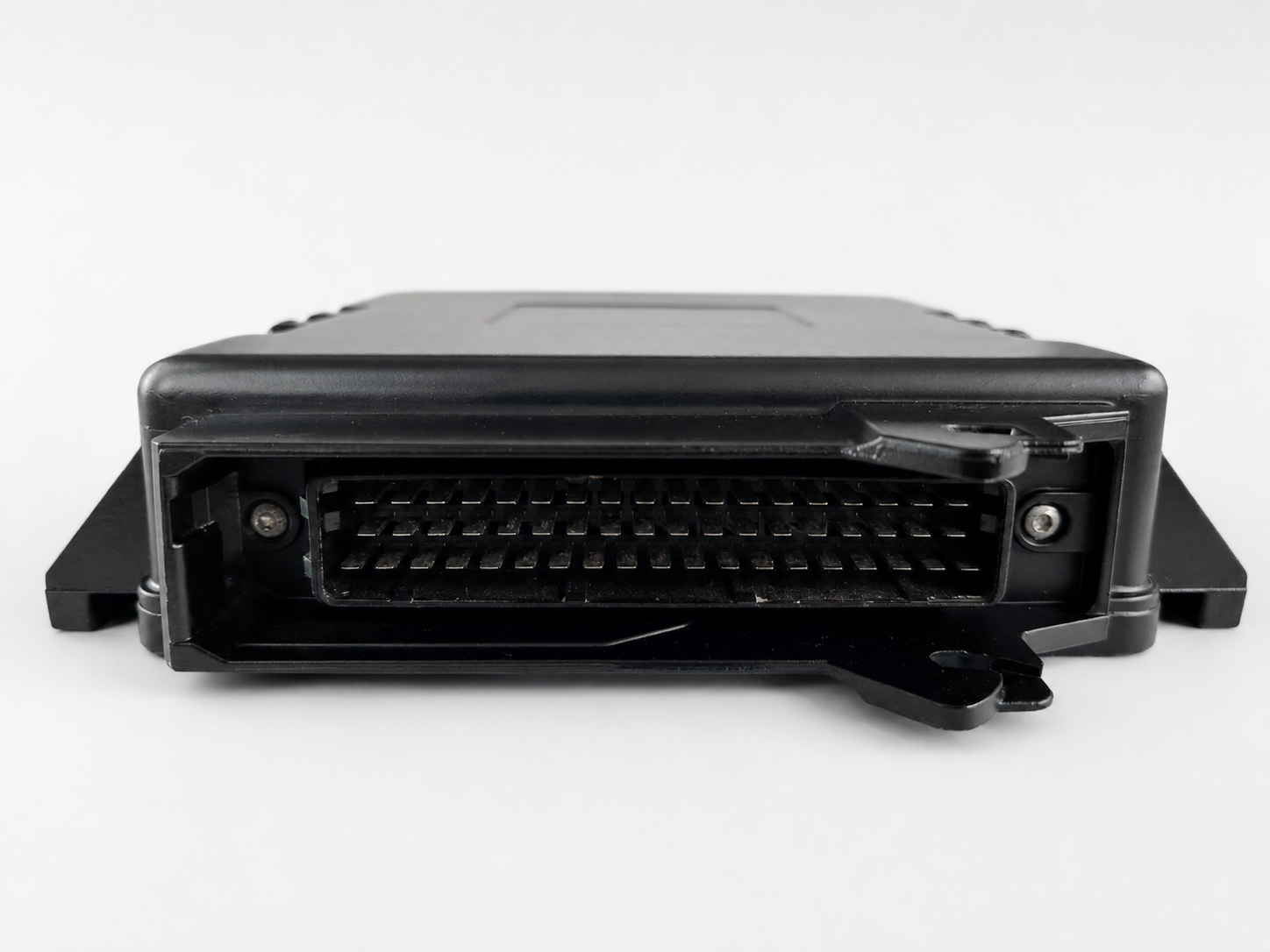
Real product images of the VasfEFI S1 PnP IAW 1AP enclosure, OEM connector and auxiliary connector area. Click any image to open it larger.
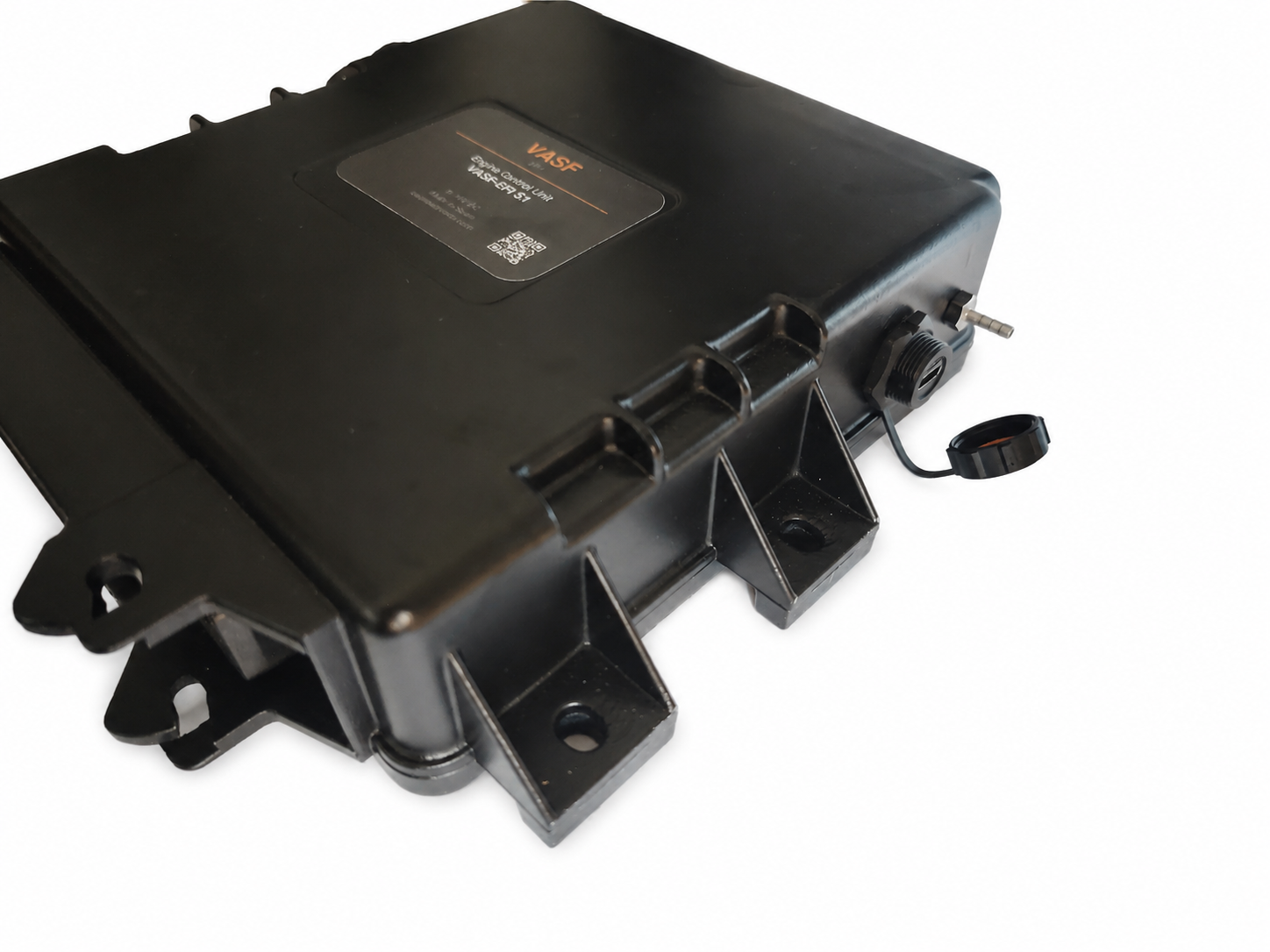
This PnP version is intended for PSA vehicles using the Magneti Marelli IAW 1AP ECU connector family, with focus on Citroën Saxo VTS and Peugeot 106 GTI / Rallye type motorsport projects.
Exact compatibility depends on the original ECU variant, engine wiring loom, sensor configuration and project requirements. The vehicle pinout must be confirmed before production or installation.
The adapter and ECU configuration are prepared around the confirmed IAW 1AP vehicle pinout, not around a generic universal wiring assumption.
A base configuration is prepared for the agreed engine, trigger setup, injector configuration and selected auxiliary functions.
Startup support and log review can be included depending on the order configuration, so the first installation is not left unsupported.
Uses the OEM-style IAW 1AP connector interface for the base engine harness where the project pinout matches the supported configuration.
Low-side output for an external boost-control solenoid. The solenoid must be supplied from a suitable fused +12 V source.
Dedicated auxiliary input for launch control activation using a clutch switch or external button.
Auxiliary analogue input for an external wideband controller output. The wideband controller and LSU sensor are not included unless specified.
Routes the OEM knock sensor signal pair and shield to the auxiliary connector, with a processed knock output returned to the S1 ECU input.
Reserved auxiliary connection for future project-specific expansion where supported by the installed S1 hardware and firmware configuration.
The auxiliary connector is used for functions that are not part of the standard OEM IAW 1AP loom, or that require external modules such as wideband and knock processing.
| AUX pin | Signal | Origin / destination | Function |
|---|---|---|---|
| 1 | KNOCK_SIG+ | IAW 1AP pin 15 | Positive knock sensor signal |
| 2 | KNOCK_SIG− | IAW 1AP pin 18 | Negative / return knock sensor signal |
| 3 | KNOCK_SHIELD | IAW 1AP pin 19 | Knock sensor cable shield. Do not connect permanently to power ground in the adapter. |
| 4 | KNOCK_OUT_TO_S1 | VasfEFI S1 pin 21 | Processed output from external knock module to the ECU |
| 5 | SENSOR_GND_REF | VasfEFI S1 sensor / reference ground | Clean reference ground for analogue signals, launch button return and knock signal reference |
| 6 | +12V_IGN_AUX | IAW 1AP pin 35 or common IAW 13/35 ignition supply line | Switched +12 V supply for low-current auxiliary electronics, such as the external knock module buck converter |
| 7 | MODULE_GND | ECU / controlled engine ground | Power return for auxiliary module electronics |
| 8 | BOOST_OUT | VasfEFI S1 pin 5 | Low-side output for boost-control solenoid |
| 9 | LAUNCH_IN / CLUTCH_IN | VasfEFI S1 pin 20 | Launch-control activation input from clutch switch or button |
| 10 | WIDEBAND_IN | VasfEFI S1 pin 18 | 0–5 V analogue input from external wideband controller |
| 11 | WIDEBAND_GND | VasfEFI S1 signal / sensor ground | Signal ground for external wideband controller output |
| 12 | SPARE_AUX | VasfEFI S1 pin 6 spare | Reserved auxiliary line for future project-specific use |